So after estimating that it would cost just about as much to rebuild/refurbish as to get a new engine, we opted for the new engine. The first question was determining what engines would fit in the engine room and how large of an engine we really needed. Looking at the numbers, we quickly realized that the engine size was really driven by the size of the propeller aperture in the hull. The propeller aperture dictates the largest propeller that can be used on the boat and the propeller size specifies the maximum horsepower that can be delivered in the water from the engine. So, we measured the aperture, calculated the maximum propeller size, determined the type of propeller (three bladed with large surface area), and identified the maximum horsepower. We then started looking at gearboxes and engine horsepower curves and identified the Beta 30 hP engine as a good match for our needs.
The Perkins was rated at 42 hP but we were going for 30 hP, were we concerned? Looking at the engine-gearbox-propeller combination, we found out that we could not effectively use anything much more than about 28 hP, as the propeller would start caveating and loose thrust efficiency. So while we "had" 42 hP, we never used them all, so we opted for an engine that was better matched to the hull length and hull propeller aperture and went with the 30 hP.
We chose the Beta 30. There was another major advantage to the 30 hP engine. By going from a four cylinder to a three cylinder engine, we were able to move the engine-gearbox forward in the engine room. After (very) careful measurements, we were able to place the engine so that the transmission (gearbox) could be removed for service without having to disconnect the engine. This is a major benefit as gearboxes can fail more frequently than engines. On our previous boat, we did not have that option and both times we had the gearbox rebuilt, we had to remove the entire engine in order to remove the gearbox. Additionally, the new engine-gearbox location enabled the shaft coupling to move forward in the engine room and this makes it accessible for precise engine alignments.
Sea trials confirmed that we indeed had plenty of power and that any larger engine would have only added weight and limited access in the engine room.
The engine replacement process was complex and multifaceted. We had to work in 3D and locate the engine in the engine room with tolerances of only thousandths of an inch (hundredths of a millimeter). The main steps involved with the engine replacement were the following:
1. Document the old Perkins engine installation, including labeling of wiring and hoses.
2. Place order for new engine with custom engine feet matching the dimensions of old engine.
3. Disconnect old engine.
4. Suspend and relocate old engine in order to remove old gearbox.
5. Disconnect gearbox from old engine.
6. Hire crane to remove old engine.
7. Refurbish engine room (including replacing all 40-year-old through hulls and hoses).
8. Replace cutlass bearing.
9. Measure, order, and install new shaft and propeller.
10. Hire crane to install new engine.
11. Install instruments panel for new engine.
12. Customize engine exhaust riser (welding stainless steel done by welder)
13. Connect engine exhaust, fuel, water, remote oil filter and electrics.
14. Align engine.
15. Commission engine and conduct sea trials.
The replacement of the old cutlass bearing was challenging as we had no information as to how to disassemble the old bronze fixture. The other big challenge was the engine alignment. What we found after having the new engine placed in the engine room was that the old engine was improperly placed in the engine room (with respect to the shaft) and therefore the custom engine mounts of the new engine were off by 3/4 of an inch (1.8 cm). In order to remedy this problem, we reworked the engine stringers and ended up with the engine in the correct location. When all was said and done, this took the better part of six to seven weeks to resolve.
After some initial sea trials last fall, we sorted out some engine mount and exhaust issues that we wrote about last fall. We are very pleased with the new engine and already have put 90 hours on it. Here are some pictures of the engine removal and installation process. We hope you enjoy.
After some initial sea trials last fall, we sorted out some engine mount and exhaust issues that we wrote about last fall. We are very pleased with the new engine and already have put 90 hours on it. Here are some pictures of the engine removal and installation process. We hope you enjoy.
Alex and Cheryl

Old Perkins 4-108 Engine

Old Engine Suspended in Order to Remove Old Gearbox
(necessary in order to be able to remove the engine through the hatch opening)

Engine Disconnected, Gearbox Removed, and Cockpit Padded Prior to Engine Removal

Old Engine (without gearbox) Hoisted by Crane

Rusted Old Engine Mounts
(Mounts had failed and were no longer providing proper engine support)

Engine Room After Removal of Old Engine (yuck!)

Removal of Old Propeller and Shaft

Disassembly of Cutlass Bearing Holder
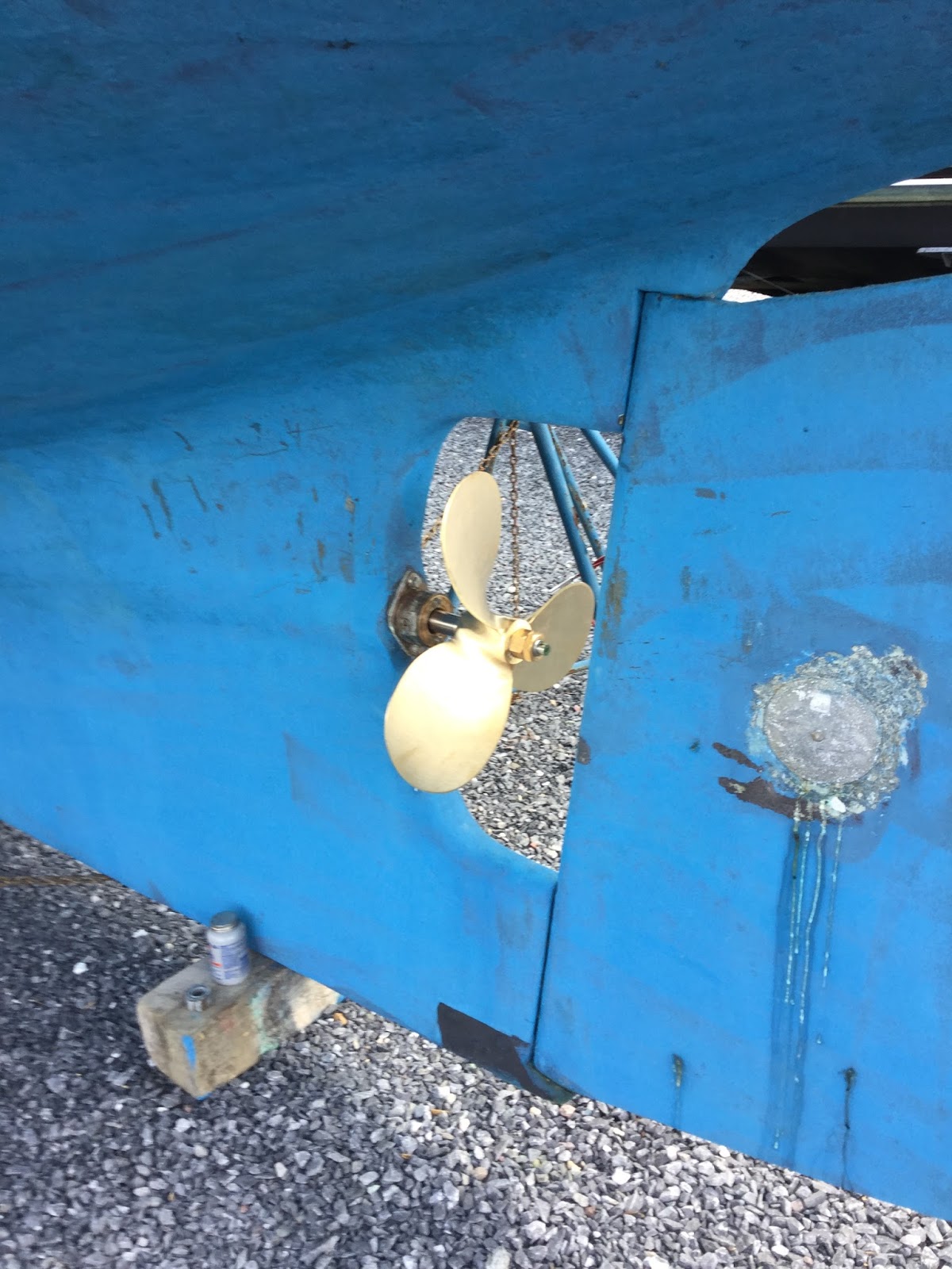
New Propeller, Cutlass Bearing, and Shaft Installed

Working on Adjusting/Lowering the Engine Stringers - Note Void next to Blue Tape

Port Stringer Re-fiberglassed

Refurbished Engine Room with Relocated Stringers and New Engine Mounts

Preparing for the Installation of the New Instruments Panel

New Instruments Panel Installed - Cockpit Port Side

New Beta 30 Engine Installed!


